|
PLM, PDM, MBE, PMI, realistic rendering etc,
have little to do with increased engineering productivity, more than likely
hinders it. Yet, these are the things the Major CAD systems are
focused. 3D modeling functionality basically has hit its end,
probably around 2010. I use that date, because it was the year that Solidworks included direct edit functionality. The Major CAD systems
know that and have to make 3D CAD more than modeling parts, just to
keeping your maintenance current. Autodesk has even given up on that
and just went directly to subscription only. It truly time to break
the hold they have on us!
The Worst to Best 3D CAD System and Why
You are Not Stuck with Autodesk or PTC Subscriptions!
So how do we establish basic optimum 3D
modeling?
Let me show you!
After I did the following simple
exercises that started as comparisons for the two CAD systems I
represent, IronCAD and ZW3D, to Fusion 360 I quickly realized they
turned into a comparison of modeling techniques. Rarely do you find
a 3D CAD dealer that is also a professional designer with tens of
thousand of design hours in manual (17 years) and 3D CAD design (37
years). Yes a total of 54 years!
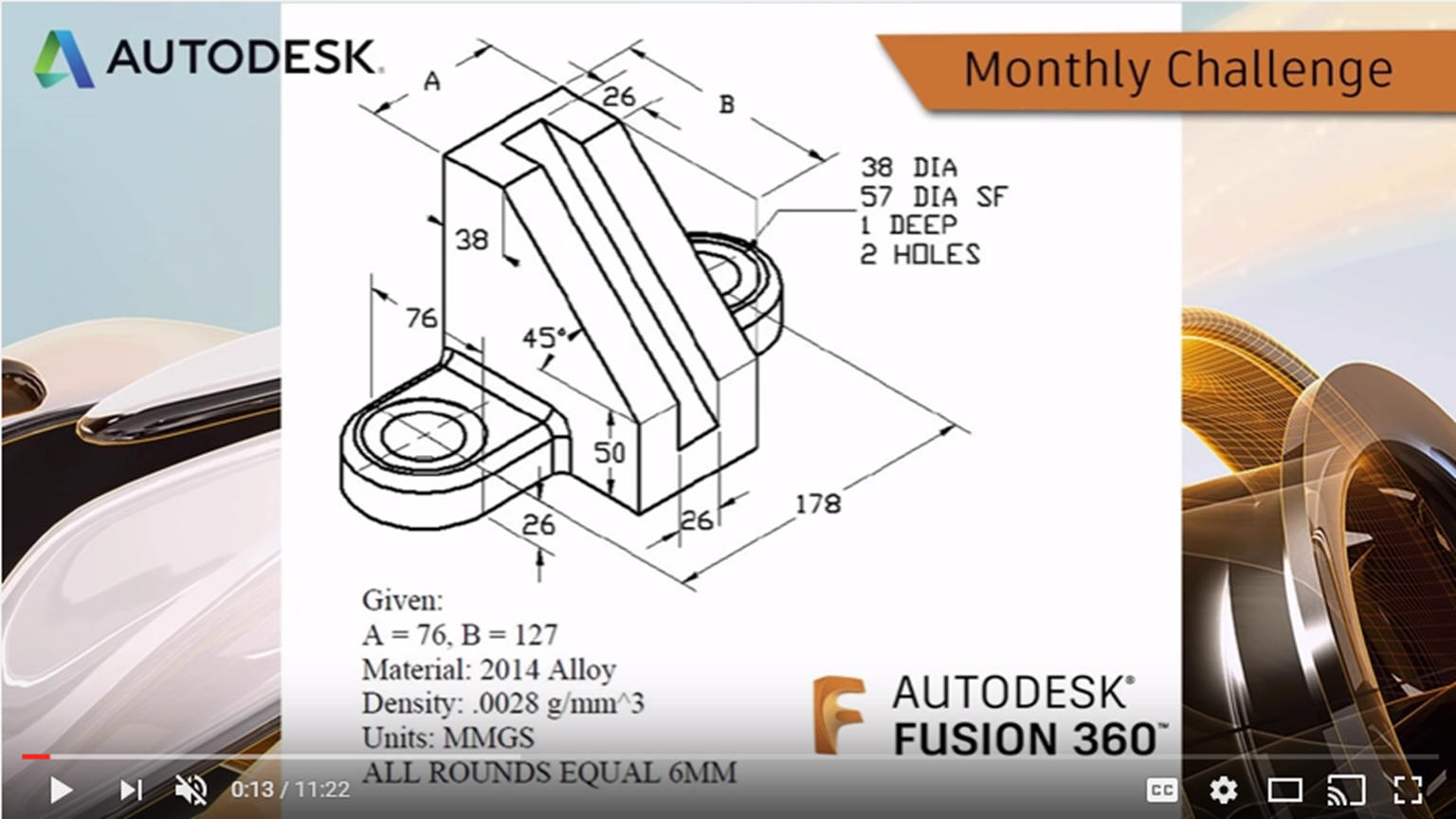 These are the latest lessons and you can see
the earlier lessons linked at the end of these articles if you are
interested. They show much different modeling techniques that you
are probably not aware. I was involved with 3D a almost a decade before the
constrained sketching 3D CAD world appeared. I now see that my
modeling techniques are much more productive. How do you know if
there may be a much simpler 3D modeling process? You watch someone
else model. These are the latest lessons and you can see
the earlier lessons linked at the end of these articles if you are
interested. They show much different modeling techniques that you
are probably not aware. I was involved with 3D a almost a decade before the
constrained sketching 3D CAD world appeared. I now see that my
modeling techniques are much more productive. How do you know if
there may be a much simpler 3D modeling process? You watch someone
else model.
IronCAD vs Fusion 360 Lesson 8
ZW3D vs Fusion 360 Lesson 8
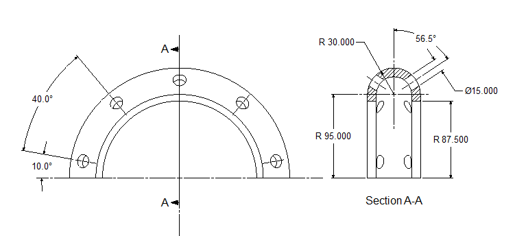 I also found some Solidworks lessons. This is one of the more blatant examples of feature based modeling as
compare to extensive sketching. I also found some Solidworks lessons. This is one of the more blatant examples of feature based modeling as
compare to extensive sketching.
IronCAD vs Solidworks Lesson Three
ZW3D vs Solidworks Lesson Three
I was shocked at the level of modeling
complexity that the Fusion 360, Solidworks, Creo, NX, Catia and
Inventor presenters did to make such simple
parts. I would have loved to blame the CAD system, but you can see
that the presenters have learned only one way to model. An
incredible dependence on fully sketched/constrained parts. They must
ask this question first "How do we sketch this part" instead of "How
do we model this part". This is a mindset! You can see the huge
difference in modeling productivity shown in the above lesson
comparisons.
Here are all of the lessons which include
modeling technique comparisons with Creo, Solidworks, Inventor,
Catia, NX and Fusion 360!
3D Modeling Techniques Defined
Now we cannot blame the presenters,
they have been trained in the Pro/e (Creo) design process. Sadly,
the 3D CAD world has standardized on this dated modeling paradigm and it
is more than likely they were trained by 3D CAD jockeys than
experienced design professionals. I will tell you if many designers,
design with this complexity, engineering is costing a company a
fortune depending on the size, of course. Sadly, there is no design
standard test that can be done. The Pro/e (Creo) design process is
heavily dependent on the intelligence and experience of the
designer. But that is just one of the many problems with this design
system.
Is 3D CAD Productivity an Oxymoron?
All you want to know about 3D CAD training!
Since the above articles were incredibly
popular. I thought I would continue them by creating an assembly in
the step by step method I did above. It gives a bit better
explanation of what the process is than watching a video. The above
ancient drawing will serve as this assembly for this exercise. I
used it before to sharpen my skills on ZW3D.
I will be doing parts in each of my
packages every weekend. You will not only see the benefits of my CAD
programs but a much different modeling technique. I will include a
drawing of each part at the end, so you can easily duplicate the
parts in your own system. If you don't have a system you can
download IronCAD or ZW3D for a 30-day trial.
Yes, both systems offer a bit different,
yet more productive way of designing. You will see the use of
primitive shapes mixed with sketching. But you can create any of
these shapes with streamlined sketching in any of the popular 3D CAD
systems and follow along. This exercise is not 3D CAD system
sensitive. It truly relates to all 3D CAD systems.
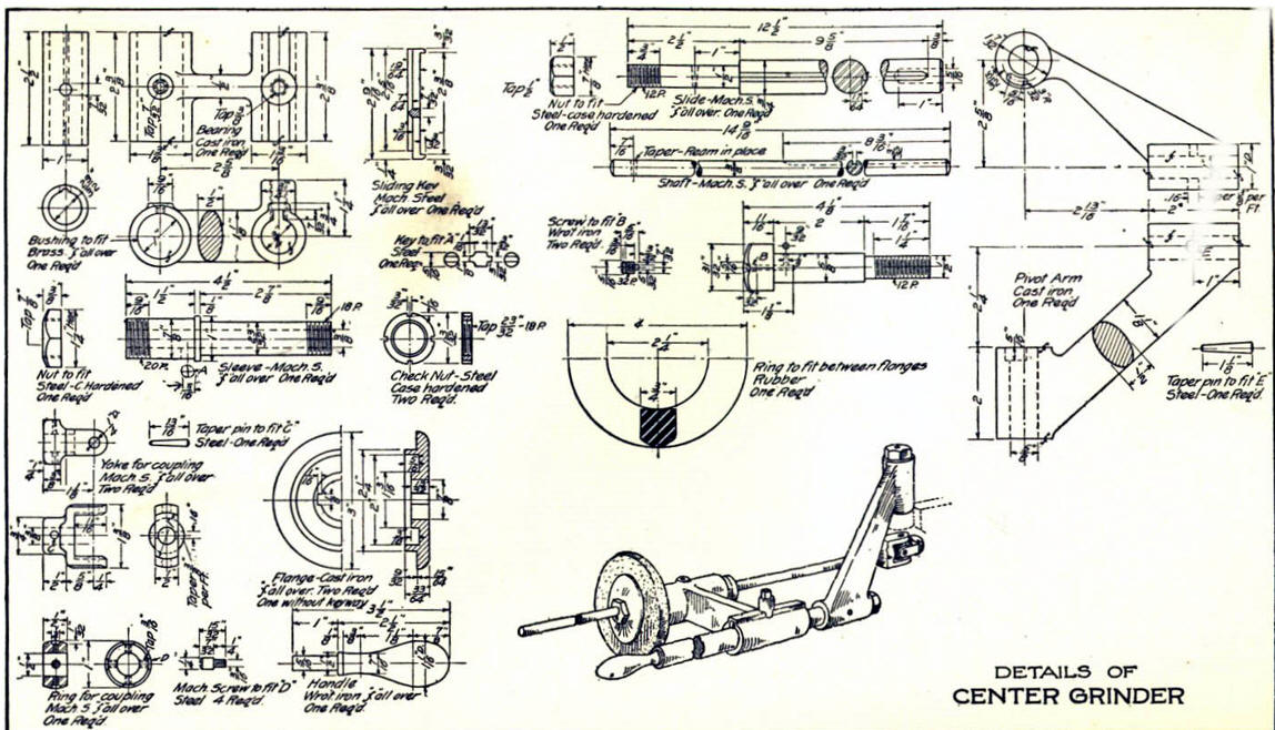
Here is a description of modeling the above
assembly in ZW3D.
LEARNING MECHANICAL 3D CAD
Here is the assembly done from the drawing above using in ZW3D Standard
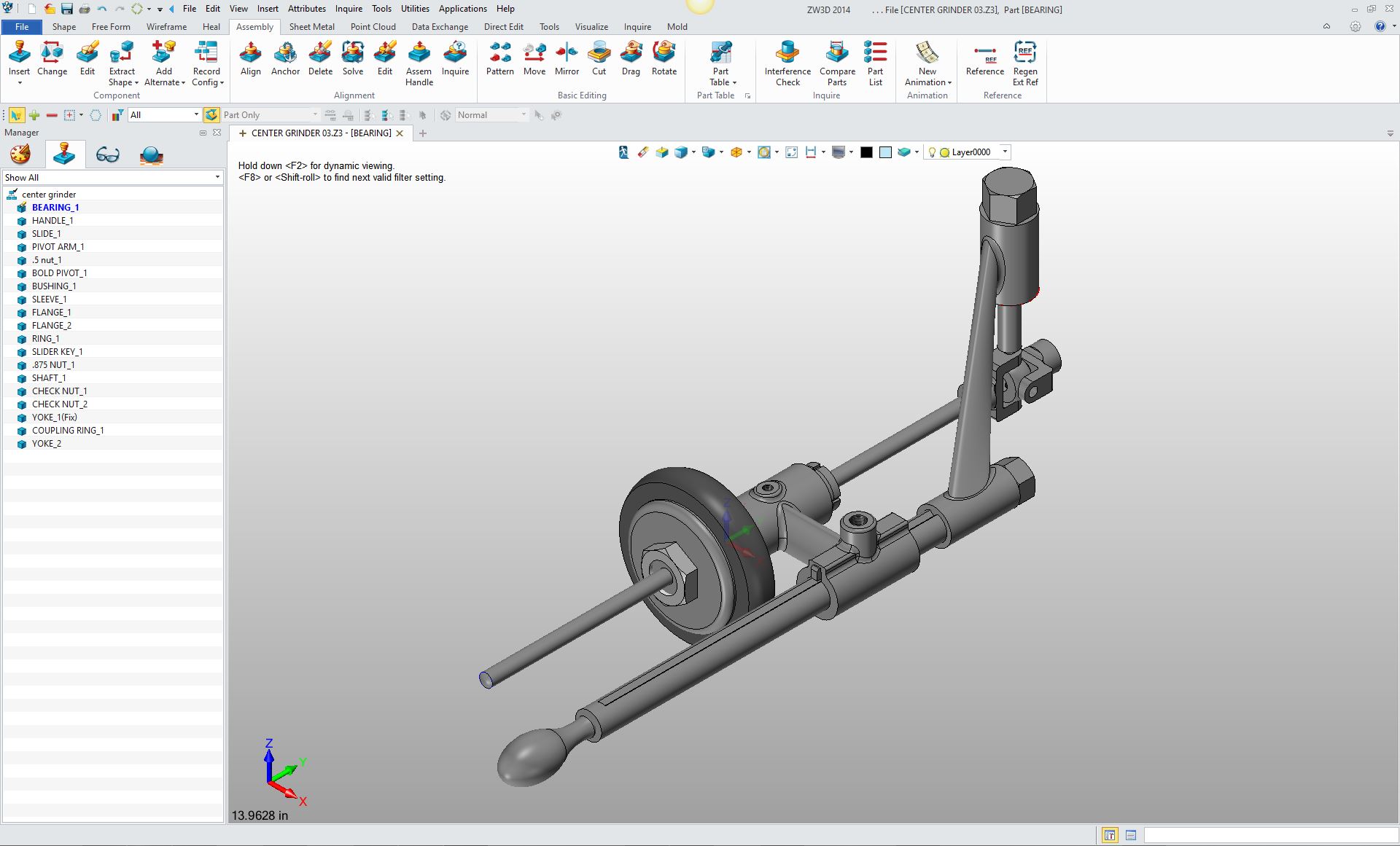
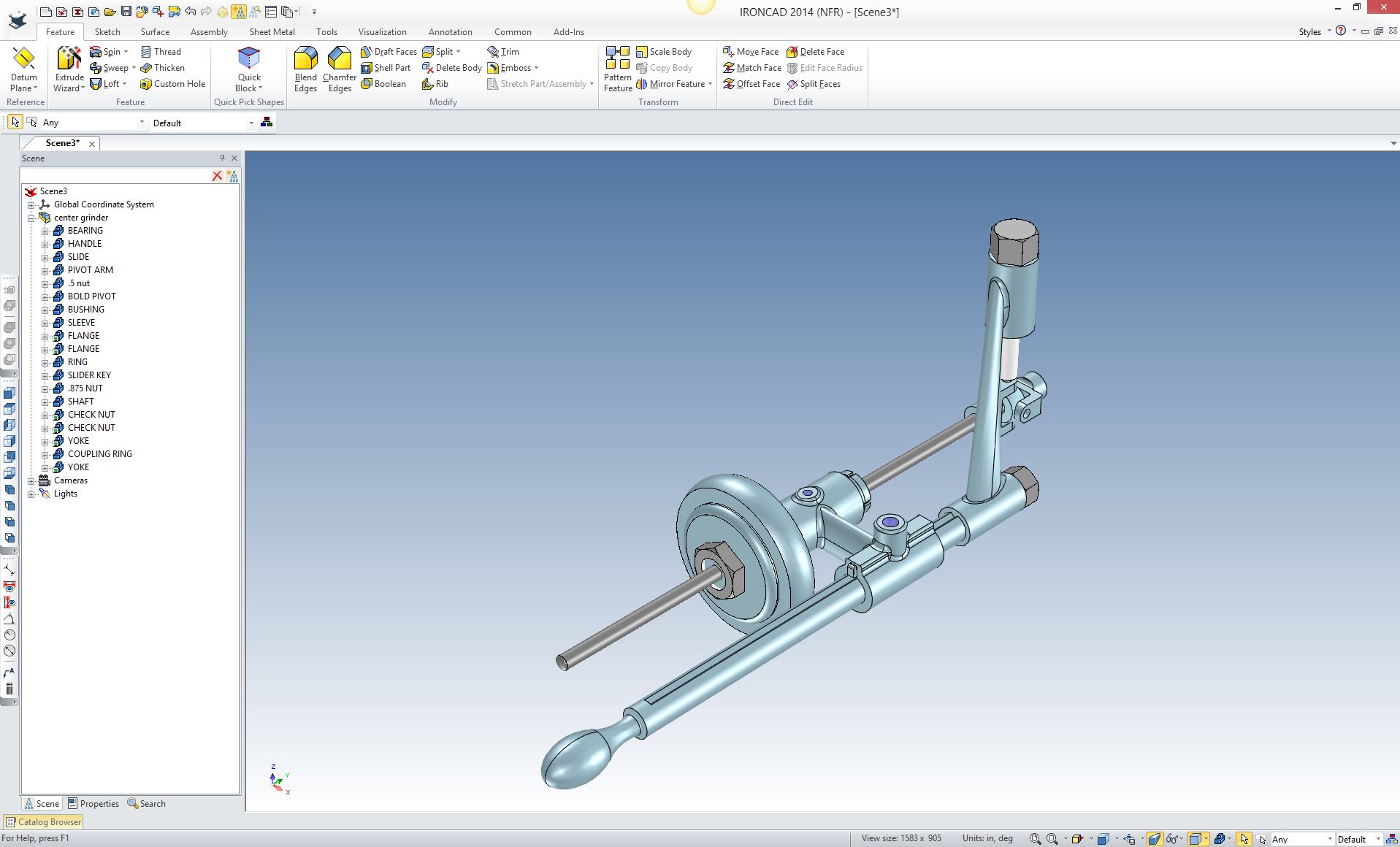
Here is the assembly exported to IronCAD using Parasolids. Notice that the names of the parts and assemblies are part of the import. This is the advantage of the parasolid translator.
Lost In Translation!
A Guide to 3D CAD
Translation Formats.
I hope you
can review this project as I create these parts in the assembly as
top down or in context modeling. Not
only will I show you a different modeling technique I will show you
the incredible advantage of designing in a single model environment.
This assembly will be in a single file in both systems.
This is a great exercise if you a budding engineer and are serious
about developing your engineering and design capabilities. You will
see now these parts were designed and how they work. Also make you
very familiar with reading drawings.
If you would like
to try IronCAD or ZW3D, please download either package or both for a 30 day evaluation.
I only ask for your information to inform IronCAD and ZW3D that
TECH-NET, Inc. has sparked your interest in our products.
3D CAD Systems Working Together
For more information or to download IronCAD or ZW3D
If you are interested in adding professional
hybrid modeling capabilities or looking for a new solution to
increase your productivity, take some time to download a fully
functional 30 day evaluation and play with these packages. Feel free
to give me a call if you have any questions or would like an on-line
presentation.
Joe Brouwer
206-842-0360
|